Friday 13 December 2013

Check Your Fuel Filler Cap O-ring Seals

Diesel or Petrol fuel filler caps are often located on an exposed area of horizontal deck or cockpit floor, particularly on sailing yachts. I recently performed a pre-purchase survey on a Nauticat Pilothouse Ketch, located at Woolverstone Marina, Ipswich. The image below shows the fuel filler cap & sealing O-ring of the starboard fuel tank of this motor-sailer. Note that the nitrile rubber has aged & hardened, resulting in numerous circumferential cracks in the O-ring, each one allowing moisture into the fuel tank. Additionally, the part of the fitting that was set into the deck was poorly designed, allowing sea water, rain water or dew to collect in the rebate that runs around the opening hole.
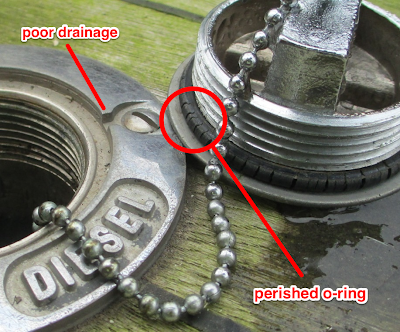
Fuel filler cap seal on sailing yacht
Typical deck-mounted filler cap

Prior to this discovery and during the survey of the rest of the vessel's fuel system, I had carefully inspected the glass-bowled primary fuel filter of each fuel tank. I noted that the colour of the liquid inside the starboard tank filter suggested that there may be water in the tank.

These were the recommendations made in the report:


1. It was found that the primary fuel filter for the starboard fuel tank had a layer of water at the bottom of the glass bowl. It is RECOMMENDED that any water in the bowls is tapped off from the primary filters for both fuel tanks. The fuel tanks should also be drained off and the contents checked for water contamination.

2. The two fuel tanks are refuelled via separate filler caps located on the port and starboard side decks. They were appropriately labelled with the text ‘diesel’. It was found that the O-ring seals that seal the filler caps were heavily perished. It is RECOMMENDED that the filler cap O-ring seals are replaced.

The new owner of the Nauticat was able to drain off two buckets of water from the starboard tank! He was lucky that there was no evidence of diesel fuel fungal growth in the tank as disel fuel with a high moisture content tends to encourage their growth.

In the UK, you can obtain new O-rings through Screwfix: www.screwfix.com/metric-o-ring-set You might not want to purchase a whole set of varying sizes just for this purpose, although it would be money well spent!

Monday 2 September 2013

Check Your Seago 150 and 175 Lifejackets

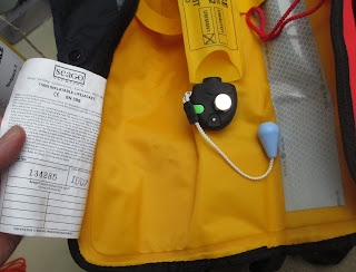
The older Seago 150 and 175 lifejackets have been subject to a recall notice for a few years now, but I'm still finding ones on boats that I survey. The first thing that I do when I discover that the item might be faulty is to remove the cylinder and this is why the jacket in the photo doesn't appear to have one.


Recall notice on Seago 150 or 175 Lifejackets
Check the date of manufacture of your Seago 150 or 175
The lifejackets are marked with the manufacturing date on the reverse of the white labels found sewn into the lifejacket below the inflation system. The lifejackets affected by both recalls all bear the following marks:
IV/05, I/06, II/06, III/06, IV/06, I/07 and II/07
If you check yours and find that you have one or more  that have a date of manufacture noted above, remove the gas cylinder from the inflation system and telephone Seago on 01825 873632.

Tuesday 4 June 2013

Gas Locker Drain: A Water Trap Could be a Death Trap

Thankfully I don't come across this defect very often. It is probably something that many owners would never notice as everything looks as though it is in good order, although in the photo below, the hose should be of the reinforced type and two hose clips should be used if the skin fitting allows this.

Yacht Survey, Gas Locker Drain
Gas Locker Drain Hose with Water Trap in U-bend
It isn't entirely clear from the photograph, but the drain hose from the boat's gas locker has a bend in it that can trap water. If water were to enter the locker, it would find its way into the tube where a small amount would be trapped. Similarly, when the boat is healed over on a close-haul, seawater could easily enter this drain. Until the water is able to evaporate, the locker drain will effectively be blocked, preventing any leaked gas from escaping harmlessly overboard. Cooking gas or LPG is a very 'searching' gas and will seep through gaps that might normally be airtight. On this vessel, it would have entered the aft heads and then into the bilge, with potentially devastating consequences.

This simple but important defect was discovered on a standard Insurance Survey on a 33' sailing yacht. Owner's are usually reluctant to have these surveys done as it is often considered that the report is purely for the benefit of the Insurance Company. The above example clearly shows that the vessel's owner can gain significantly from having a thorough survey performed on their craft, even if they think that they know their boat inside-out.

Tuesday 19 March 2013

Domestic Plumbing Hardware Used on Boats

It might be perfectly acceptable to use PVC plumbing fittings on the vessel's fresh water system, but if one was to fail, I would still be rather upset if the contents of my water tank were to sit in the bilges for some weeks whilst un-attended on her mooring. However, during my survey work I often come across more serious situations like the one shown in the photograph below. It's not uncommon for an owner to search amongst the shelves of a chandlery, looking for a marine-grade fitting of a specific size. After a frustrated search he finds what he's looking for, but neglects or forgets to consider the items' suitability for the application.

In the situation shown in the photo, a domestic plumbing fitting has been installed in a location that is below the waterline. The hose and fittings (un-reinforced hose and with single clips) are for the generator exhaust coolant outlet on a 51' motor cruiser. Even above the waterline, this situation could cause significant ingress of water if the relatively weak fitting were to fail: The generator's coolant would be pumped directly into the engine room and is also in close proximity to the vessel's batteries. In the situation shown, the hose attached to the 'un-reinforced PVC fitting' would drop down, allowing water to flow into the boat.


In this example, the skin fitting is about 12 inches below the waterline and the internal diameter of the hose is about 1 inch. For a length of hose such as that seen in the photo, the resulting flow rate will be around 9 gallons or 4 buckets of water per minute. Of course, the vessel's pumps may be able to handle this amount, but in this case a few low cost preventative measures would minimise the chances of this scenario occurring.

For advice on the installation of your vessel's skin fittings or through-hulls, contact fieldhouse-yacht-surveys.com
PVC skin fitting on yacht generator exhaust system
Generator Exhaust System

Monday 12 November 2012

'Stainless Steel' Hose Clips - They Do Corrode!

Not surprisingly and for a good reason, I find that a significant proportion of the time taken to perform a pre-purchase or insurance survey is taken up by the inspection of the boat's skin fittings and associated hoses & clips. I have already described in an earlier blog the all-too-often found skin fittings and seacocks that are made from brass, but another very common finding is the use of hose clips made from poor quality materials. As with the choice of brass material for the skin fittings, manufacturers will select a poorer grade material in order to cut production costs, thus maintaining an acceptable profit margin in an ever more competitive market place.

As part of my routine when inspecting the hose clips, I always check them with a magnet. If the magnet sticks, then I know that the screw, housing or band of the clip is made from mild steel or an inappropriate grade of stainless steel. This check can then be confirmed with a close visual inspection, using a mirror if necessary, looking for evidence of corrosion on the screw or on the band where it is concealed by the housing. Where access permits, I then wield my medium-sized hammer.

The image below shows a result from such an inspection. It was in the stern locker of a 43' Beneteau. It's not easy manoeuvring oneself inside such a locker area, although I've squeezed into smaller spaces on smaller craft. The clip was one of two that was used to secure the engine's exhaust hose to the skin fitting. I could see that the 'stainless steel' clip had been corroding, but it was the light strike from the hammer that broke the band at the point at which it contacts the screw.

Corroded Stainless Steel Hose Clip
Also note that the band of the clip shown in the photo has the kind of serrations that perforate the band, rather than the kind that are pressed into the metal. The perforated type seem to be much weaker in my experience.

The screw, although formed from stainless steel, was most likely a different grade to that of the band and housing. Within a salty and damp environment, the resulting galvanic cell had contributed to the corrosion and weakening of the band. The adjacent clip on the exhaust hose didn't fail when struck with a hammer, but it certainly appeared to be rusting at a similar rate. If my client had gone ahead and bought the boat, it probably wouldn't have had a survey for another five to ten years and in that time both clips would have possibly failed.

One of the most satisfying aspects of being a yacht surveyor is finding defects such as this and then thinking to ones self: If those clips had failed in a heavy sea, at night and whilst motoring (not an uncommon combination), the engine exhaust coolant would start to flood the boat, with sea water entering through the hole in the transom. Would the crew have found the cause in time?

This Winter:

  • Two clips per end fitting where the connection is under the waterline or where the hose coming adrift could cause flooding
  • Check clips with magnet
  • Check for rust on clips
  • If in doubt, remove clips and check for corrosion where band is under the screw
  • Check that clips are tight enough


Wednesday 31 October 2012

Stress Cracks in the Gel-coat of the Cockpit Coaming

Late last year I had an excellent opportunity to spend a few days in Camaret-sur-Mer, which is in the Finistère department in north western France. My client was interested in purchasing a 1988 Beneteau 535E sailing yacht and had asked me to go out there to survey it. I'm not going to go into the details of the survey here, but if you are interested, there's a link to the survey report on the sample reports page of my website.

Just the other day on a boating chat forum I saw a discussion thread that reminded me about a particular defect that I had found on the boat. The topic was asking about the best way to adjust the backstay tension on a masthead rigged boat. The Beneteau that I inspected in France was a Bermudian sloop with a masthead rig. The single backstay featured a hydraulically operated tensioner, adjusted by a winch handle. It appeared that the backstay tension had been set up at some point as there was a mark on the tensioner to indicate an optimum or maximum tension that should be applied.

I don't have conclusive proof, and I never suggested this in my report (keeping to the facts!), but I suspect that the cracks in the cockpit were related to the rig being over-tensioned at some point. If not, then the boat had certainly seen some heavy sailing. The photos below show the cracks.

Starboard cockpit coaming
They were located on both sides of the cockpit. The photos don't illustrate this, but the texture of the cracking was very rough and one could see that the gelcoat between the cracks had 'bunched up'.

Close-up of gel-coat cracks
As a Surveyor and Professional Engineer, I don't find it hard to visualise that as the backstay is tensioned, the deck goes into compression and the longitudinally stiff coaming is forced forwards and into the relatively flexible panel that is the saloon aft bulkhead. The concentration of stress at this corner is higher than adjacent material, leading to localised deformation and damage. Without being able to access the internal surface of the bulkhead and coaming, I was unable to establish whether the laminate had been damaged in this area. Hammer testing of the area was inconclusive, but the permanent deformation of the gel-coat suggested that some damage to the laminate had occured.

For this defect, I recommended that: The damaged gel-coat is cut back to sound laminate. The laminate should then be thoroughly cleaned and dried. Any removed laminate shall be replaced and the repairs finished with epoxy gel-coat. Additional laminate should be applied to the internal surface of the cockpit and bulkhead in these areas in order to stiffen the coaming to bulkhead join and to decrease the likelihood of this problem recurring.

Thursday 25 October 2012

Dezincified Propeller

Dezincified is a term that never seems to agree with my computer's spellchecker, but it is fairly well accepted within marine surveying circles. To quote Nigel Warren's excellent book on Metal Corrosion in Boats, dezincification is the 'gradual dissolving of the zinc content of brass leaving a spongy mass of copper: although the shape of the article is maintained its strength is virtually nil'. Well you may say to yourself 'phew, I'm safe as my prop is made from Manganese Bronze'. Unfortunately this grade isn't a bronze, but a high-tensile brass of 60:40 Copper and Zinc and dezincifies readily. The photograph below shows a nine year old propeller off a Bavaria 49, kept in seawater, showing all of the signs of dezincification. I can't say for sure, but it is likely that it was made from Manganese Bronze.

Dezincification leaves the item with virtually no strength

Don't panic just yet, in practical terms a manganese bronze propeller on a GRP, steel or timber boat is acceptable, just make sure that a sacrificial anode is fitted, wired up, reasonably close to the propeller and renewed regularly. The anode on this boat was heavily wasted and probably too far gone. This suggested that it had at some time been doing its intended job, but electrical continuity between the propeller and the anode couldn't be found with my multimeter. If you check your own, the resistance between the two should be 1 ohm or less. An additional anode attached directly to the propeller shaft would give further protection.

Replace anodes when about 50% wasted and never, ever paint them!

Contact www.fieldhouse-yacht-surveys.com if you want help with checking your boat's stern gear or skin fittings during this Winter's lay-up period.

Thursday 27 September 2012

Bronze Skin Fittings, or are they Brass?

While surveying a French sailing yacht today in Swanwick Marina near Southampton, built in 2001, I managed to break a seacock with a small strike from a hammer. The following photo was the result:


Take a look at the colour of the failed material - a bright rosy pink. I took a knife blade to the broken edge and could cut into it as if it were a soft plastic. The zinc has leached out of the brass/bronze, leaving a material with no strength. If the fitting had failed whilst at sea, there would have been a fair rate of water in-rush and it may have been some time before the crew would be able to find the source of the flooding. If it had failed at night, the batteries would have become submerged very quickly, losing lighting and engine starting capability. It is for this reason that all boat skippers should know the whereabouts of all of their skin fittings and seacocks. I always recommend in my report that each skin fitting should have an appropriately sized softwood bung lightly taped to the adjacent hose. If the seacock fails in this way, the bung can be quickly located and forced into the hole to stem the flow of water.

Moving on from the failed fitting, I aggressively pulled on the hoses of other fittings and hit the seacocks with a light hammer. The following photo shows the result:


Needles to say, my report will recommend that ALL skin fittings and seacocks below the waterline are replaced with marine grade bronze. The brokers were initially a bit displeased, but soon joined in with the breaking of a good number of seacocks.

I suggest that any boat owner checks their seacocks this winter, but only when the boat is out of the water. Give the hose a good sideways pull, strike the seacock body with a hammer. If in doubt, remove the skin fitting and inspect closely. It is not possible to visual differentiate between brass and marine grade bronze, although some seacocks and skin fittings have an identification mark on the body.

For further advice, find our contact details on our website and feel free to give us a call or write an email.


Wednesday 19 September 2012

Check your Plastic Skin Fittings!

Moulded white Nylon Skin Fittings: Millions of boats have them, many have them too close to the waterline, some even have them (incorrectly) under the waterline. The un-reinforced nylon material is tough enough in the right application, but they don't stand up to many years of exposure to sunlight.
The black ring is a crack
The one in this photograph has quite clearly cracked around the inner circumference. You can imagine that when this skin fitting was installed, the large nut on the inside would have been screwed on quite tightly. This puts the plastic between the nut and outer flange into tension, creating stresses in the material. Over a number of years, sunlight will attack the nylon and slowly weaken it. Eventually, a crack may develop in the weakest and most highly loaded area. The crack propagation will be accelerated by impact, such as when the boat rubs alongside a pontoon or mooring pile.

This Winter Lay-up:

Closely inspect all of your plastic skin fittings. Look for signs of cracking around the inner circumference. Look at the condition of the nylon on the outside: Is it crumbly or powdery? Consider replacing if you are unsure. From the inside of the boat, apply a sideways pressure to the skin fitting. If there is movement, look closely for external cracks or determine if the fitting needs to be re-bedded.

Consider an Upgrade:

If the nylon skin fitting is close to the waterline, say less than 250mm above, consider replacing the nylon fitting with a marine bronze one. To be extra safe, use two hose clips when securing the hose to the fitting. American Standards specify that any fitting below the 'heeled waterline' should have a seacock fitted. For further advice, feel free to call us. Our contact details can be found on our website: www.fieldhouse-yacht-surveys.com